This page is aimed to offer some detailed information about a visual effect which is frequently discussed within the binocular users communities, yet hardly understood. I hope that the animations on this page will be useful, and that they may contribute to the general understanding of this century old problem of adding the proper amount of distortion to visual instruments.
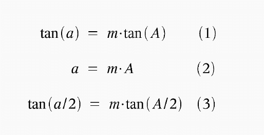
While making an optical instrument, the designer has got the freedom to choose among various different parameters that characterize image properties. Among them is the amount of distortion, usually defined along with the design of the binocular eyepiece. Albrecht Koehler has presented three different transformation formulas on his web page (German language), which are shown in Fig. 1:

Fig. 1: Tangent-condition (1), angle-condition (2) and circle-condition (3)
Here, 'A' refers to the object angle, which is the angle between the optical axis (direction of view) and the object, also denoted as true angle. 'a' is the angle of the corresponding image with respect to the center of field, also called apparent angle. Finally, 'm' is the (paraxial) magnification of the binocular. Hence, these transformations define how exactly the true angle of every object is mapped into the corresponding apparent angle, and in this way they determine the properties of the image generated by the binocular.
Traditionally, i.e. up to the first half of the 20th century, most binoculars were designed according to the tangent-condition, as had been suggested by Airy as early as 1827 (references to historical facts are found on the web page of Albrecht Koehler). The tangent condition apparently delivers an undistorted image, because radial distances in object space, which are proportional to tan(A), are linearly mapped into radial distances in image space, tan(a), with the constant factor 'm'. If we were dealing with cameras here, then there would exist no dispute about which imaging equation delivers a perfectly undistorted image: The tangent condition.
However, doubts remained whether the same holds true when the instrument is used in combination with the human eye. These doubts were supported by frequently re-emerging complaints raised by officers on the battlefields of the both World Wars: Whenever such a binocular, designed after the tangent condition, was panned, then the image seemed to be rolling over a convex surface. This phenomenon is nowadays called globe effect, or rolling ball effect, and there exist reports on people suffering motion sickness after using these binoculars for panning. In military applications, binoculars are often employed to check wide areas for enemy movements, and here the artificial dynamics of the rolling ball may in certain situations distract the observer who fails to detect enemy activities on the battlefield.
During the first World War, the three notable optical designers Whitwell, Tscherning and Weiss had already suggested to abandon the tangent-condition and, instead, to employ the angle-condition (2) for binoculars which are designed for surveillance applications, and in 1946, the Zeiss optical designer Hermann Slevogt published his studies, that were based on much earlier work of Hermann von Helmholtz, suggesting the implementation of the circle-condition, Fig. 1, equation (3), as a replacement for the tangent-condition. From 1947 onwards, Zeiss indeed decided to abandon the tangent condition and to add a certain amount of pincushion distortion to their binoculars, and most of the notable binoculars manufacturers world wide would soon be following up along the same path. Since then, most of the binoculars on the market are featuring a certain amount of pincushion distortion in order to eliminate the impact of the globe effect.
How is it possible that the pincushion distortion is able to compensate for the globe effect? And which amount of distortion is actually required to achieve that goal? A detailed analysis of the relationship between both distortions is carried out in the following sections.
The first question to be addressed is: What exactly is happening when the binocular is used in combination with the human eye? In 1867, Hermann von Helmholtz claimed that the image of a checkerboard, that features a certain amount of pincushion distortion, does suddenly appear regular when viewed close up. This experiment can be used to 'measure' the amount of distortion generated by our vision (see also the work of A.H.J. Oomes et al., Perception 38, p. 1284, 2009). We shall repeat this experiment here, but first of all generalize the imaging equations of Fig. 1 in the following way:

Fig 2: Generalized transformation formula with distortion parameter 'k', meanwhile known as Merlitz-condition [1].
As usual, 'A' corresponds to the real angle of the object with respect to the center of field, 'a' to the corresponding apparent angle, 'm' to the magnification, and 'k' is a new parameter that unifies the three equations shown in Fig. 1. With the choice k = 1, the tangent condition is recovered, k = 1/2 yields the circle condition, and it can easily be shown that the limit k -> 0 would deliver the angle condition.
I have generated checkerboards with different amounts of pincushion distortion (Fig. 3). The images are constructed in such a way that they resemble the image space of a 10x binocular with 7 degs. true field of view, with a distortion evaluated according to the equation in Fig. 2. These images have to be viewed close up, so that their circular boundary appears under the same apparent angle as the apparent angle of view of the binocular (i.e. about 70 degs.). The black bars below the images indicate the correct distances. Which checkerboard appears regular under these conditions?
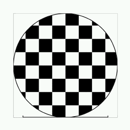
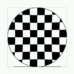
Fig 3: Checkerboards with different amounts of pincushion distortion. From left to right, upper row: k=1, k=0.7, lower row: k=0.5, k=0. Click to open the full screen version, which has to be viewed close up (distance equal to the black bar below the image), with one eye, strictly fixating the center of the board. The curvature of the lines has to be judged through peripheral view, without shifting the direction of view off center. Which checkerboard looks regular then?
I asked members of two German Internet forums to carry out that test and obtained different results. This indicates that the amount of distortion generated by the human vision might differ from individual to individual. The majority of test persons opted for the board k=0.7, but a significant number of individuals did still notice a slight barrel distortion with the k=0.7 board and at the same time a slight pincushion distortion with the k=0.5 board. This would indicate that the ideal checkerboard might have a distortion in between, perhaps around k=0.6. This is not exactly in agreement with Helmholtz's original proposal, that suggested the circle condition (k=0.5) to deliver an undistorted image to the eye. However, the results reported by the test persons displayed a large degree of scattering, which indicates significant individual differences. I also noticed that the group of eye-glass wearer delivered less consistent results compared to the test persons who don't have spectacles. It is a well known fact that glasses for short-sighted people often add a certain amount of barrel distortion, and this may generate a significant bias of the Helmholtz experiment.
In any case, this experiment verifies that our visual imaging system introduces a certain amount of barrel distortion to the image space. This barrel distortion eliminates an equal amount of pincushion distortion from this image space and hence generates the impression of an undistorted image if both distortions are matching in strength. Mathematically, we have to take care of this additional transformation by introducing the following formula:

Fig 4: Visual transformation formula with distortion parameter 'l'. The apparent angle 'a' is transformed into the radial distance 'y' in visual space.
Here, the new parameter 'l' stands for the distortion generated by the human vision. This formula transforms the image space, that is produced by the binocular, into the visual space, being the perceived image when the image space is watched close up. Let us assume a visual distortion parameter of l=0.6, then the checkerboards appear as shown in Fig. 5:
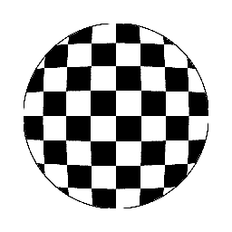
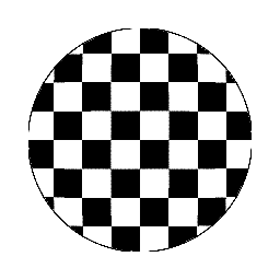
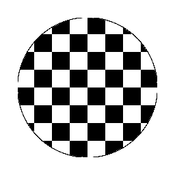
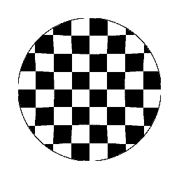
Fig. 5: The same checkerboards as shown in Fig. 3, after transformation into visual space. Here, a visual distortion parameter l=0.6 was assumed.
The image generated after the tangent condition (k=1, upper left) now displays a significant amount of barrel distortion, and the one after the angle condition (k=0, lower right) displays a pincushion distortion. The both other boards are nearly undistorted, the k=0.7 example (upper right) featuring a very light barrel-, and the k=0.5 example a similarly weak pincushion distortion. There is another interesting fact to be noticed: Some of the test persons reported on the impression of an apparent image curvature. They observed a convex curvature in case of the tangent condition (k=1) and a concave curvature in case of the angle condition (k=0), while the circle condition (k=0.5) and the k=0.7 checkerboard appeared almost flat. This can be interpreted as an intrinsic curvature of our visual space, that is compensated through the binocular when using a pincushion distortion of about k=0.6.
Such an intrinsic, convex curvature would explain another daily life experience: Why does the curvature of the night sky not resemble that of a half sphere? It seems to have a concave shape, but appears to be somehow flatter than a semi-sphere, rather looking like the inside of a flat bowl, or a wok. In fact, if our visual distortion parameter were equal to unity, l=1, then we would get the impression of a perfect semi-sphere, and in case l=0 the sky might appear flat. A value somewhere in between, e.g. l=0.6, would very well explain our perceived curvature of the night sky.
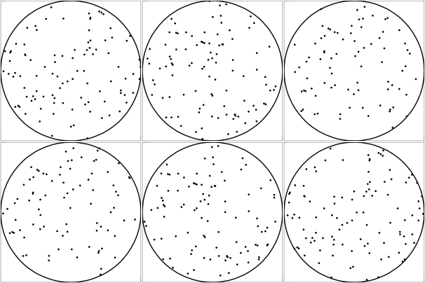
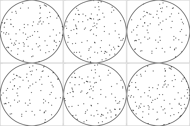
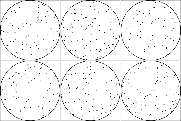
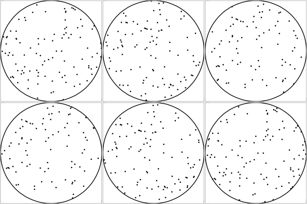
Fig. 6: The visual space, when the binocular is panned over the night sky. Binocular distortion: k=0 (angle condition, upper left), k=0.5 (circle condition, upper right), k=0.7 (lower left), k=1 (tangent condition, lower right). Here, a visual distortion of l=0.6 is assumed.
Figure 6 shows what happens in visual space (assuming l=0.6) when the binocular (10x power and 7 degs. field of view) is panned over the night sky: The angle condition exhibits a residual pincushion distortion that, behind the ocular, delivers the impression of a concave curvature of the image (upper left). Such an effect can be observed e.g. with the Zeiss Jena 7x40 NVA EDF, or the Hensoldt 8x30 Fero-D 16. The tangent condition (lower right) delivers the impression of an image that is rolling over a convex surface - the globe effect. Astronomers are well familiar with this effect when using orthoscopic eyepieces (which are designed after the tangent condition). This convex surface is nothing else but the curvature of our visual space. Both intermediate cases (k=0.5 and k=0.7) deliver a rather flat image while panning, without the impression of any significant curvature. Note that a visual barrel distortion of l=0.6 was assumed here, so that a binocular with an equal amount of pincushion distortion, k=0.6, would exactly eliminate the visual curvature. The latter may of course differ from person to person, which could explain the fact that some individuals seem to be less sensitive to the globe effect than others.
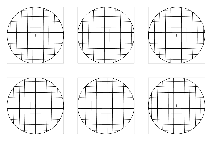
So far we have assumed that the observer keeps his direction of view fixed into the center of field. In reality, this is not the case, and the binocular is often used with the rolling eye, thereby adding complexity to the transformation equations. The Fig. 7 shows what happens to a regular pattern (e.g. a wall made of bricks) when imaged with binoculars of different degrees of distortion, and viewed with the eye fixating the center of the image (left column) or when pointing 25 degs. (apparent angle) below the center of field (right column). For this example, once more a 10x binocular with 7 degs. field of view was chosen, and a visual distortion parameter of l=0.6.
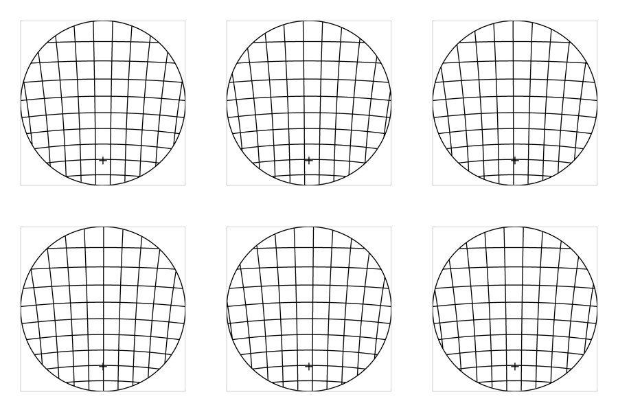 k = 0 (angle condition)
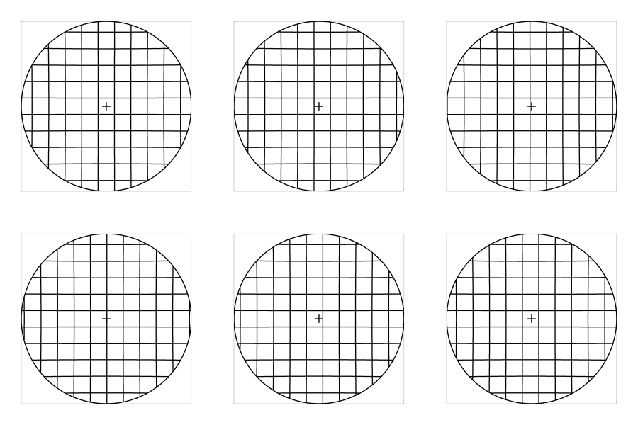
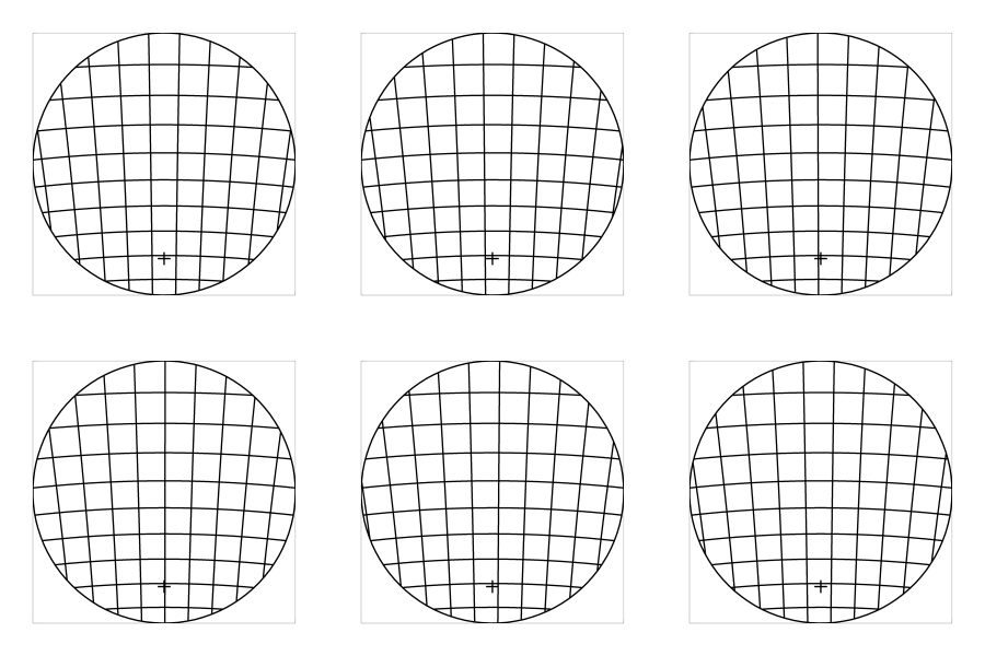 k = 0.5 (circle condition)
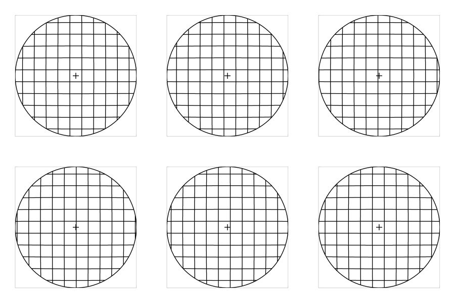
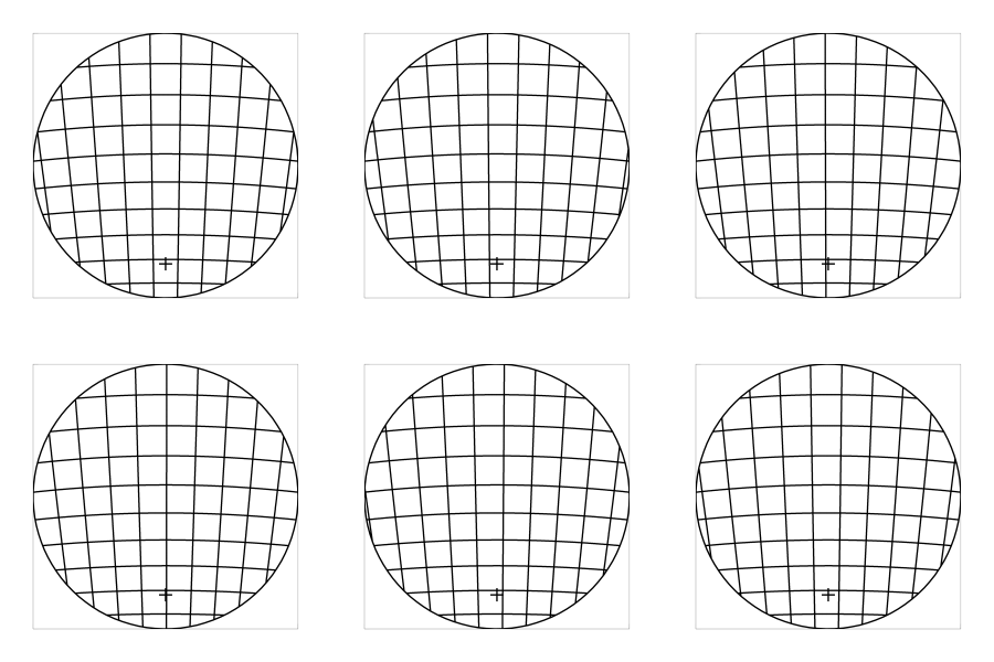 k = 0.7
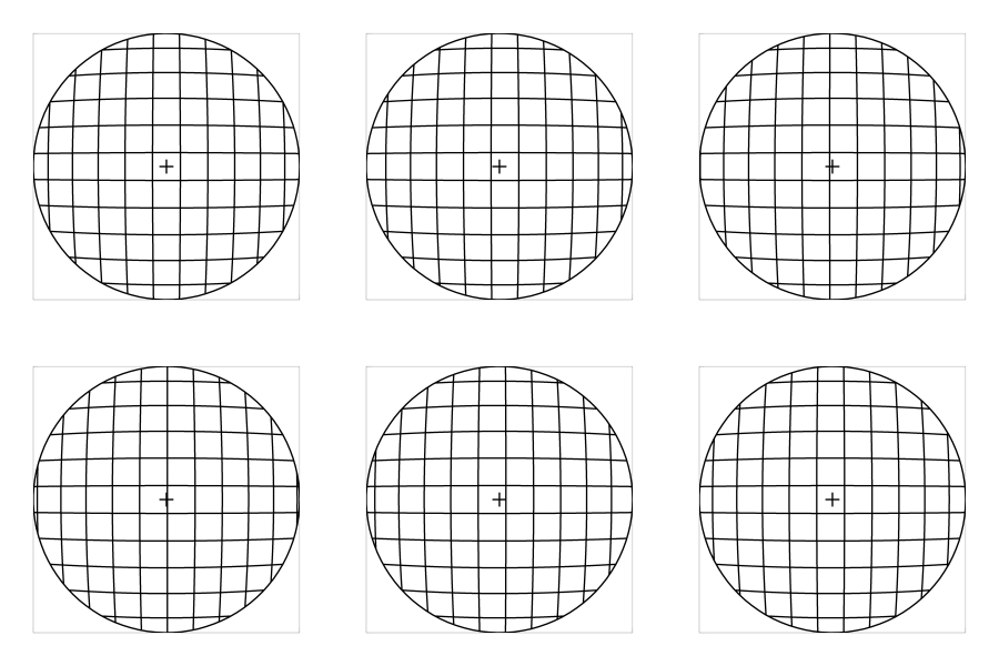
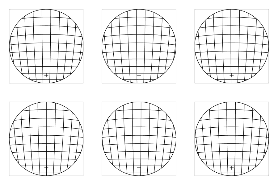 k = 1 (tangent condition)
Fig. 7: The off-centered view: To the left, the direction of view is centered, to the right, it is offset 25 degs. below the center of field (cross). Again, a visual distortion parameter of l=0.6 was assumed. In this example, the choice k=0.7 seems to deliver the best overall imaging, i.e. a good compromise between globe effect and residual pincushion distortion.
The angle condition (k=0), but also the circle condition (k=0.5) are adding a significant amount of curvature to lines near the off-centered direction of view (cross). To the human eye, these binoculars appear to deliver a clearly visible pincushion distortion. For the case k=0.7 this distortion is already quite weak, and for the tangent condition (k=1) the horizontal lines appear perfectly straight near the direction of view. In this case, the observer gets the impression of an undistorted image. There exists an overall barrel distortion, but this is not very obvious as long as the image remains still, because the curved lines are far away from the direction of view that coincides with the focus of attention. However, the same barrel distortion becomes obvious when the binocular is panned and the image is rolling in front of the eye as a global entity, clearly displaying the globe effect with the tangent condition. The animation does also nicely demonstrate how the angle condition (k=0) seems to create a concave curvature of the image. The strength of this curvature coincides with the impression our bare eyes receive when observing the sky. Therefore, the angle condition simulates the natural curvature of the sky and may be ideal for handheld astronomers binoculars.
When frontally watching a wall with our bare eyes, we get the impression of a convex curvature as shown with the tangent-condition (k=1). However, we do not seem to notice that distortion in daily life. The reason is: Our brain does not image the wall instantaneously, but the eye is scanning around and the final image is composed out of multiple local images. Each of them delivers the impression of (locally) straight lines to the rolling eye, and the brain is thus composing the final image as a flat, undistorted wall, successfully suppressing the residual barrel distortion of our visual space. However, it is possible to observe a globe effect with the bare eye, while walking along the wall at a close distance (around 1m), and carefully watching the curvature of the moving wall surface with a single eye. Under these circumstances, the curvature of our visual space becomes evident.
The binocular generates its image inside the image space. Unlike a camera, which would record that image space directly onto its photographic sensor, the image undergoes an additional transformation when perceived by the human eye, thereby picking up a barrel distortion, or convex curvature, that eventually generates the globe effect of the panning binocular. This effect can be eliminated with the help of an equally strong pincushion distortion in the binocular design. However, once the eye is pointing off center, this pincushion distortion is showing up again, leading to an image degradation. It appears that a good compromise is found with a distortion that is somewhat weaker than the circle condition (k=0.5), perhaps near k=0.7, because here the residual pincushion distortion, perceived with the rolling eye, is already very weak, and so is the globe effect with the panning binocular.
Naturally, the ideal amount of distortion is known only after an accurate determination of the visual distortion 'l'. If the latter does in fact exhibit strong inter-individual fluctuations, then obviously the ideal binocular distortion cannot exist. In this case it might be worth thinking about oculars with tunable amounts of pincushion distortion. Here, each individual user would be able to optimize the binocular to his eye, and, of course, to the application he has got in mind. The tangent condition would be suitable for architecture studies, the circle condition e.g. for horse racing, and the angle condition for astronomy, since it would simulate the natural concave curvature of the night sky through the ocular. Perhaps, one day the binocular manufacturers will offer eye-tests on their websites, similar to the Helmholtz checkerboard test, through which the buyer could test his visual distortion before ordering his individually optimized binocular.
As it appears to be the case, the predictions made above have been verified during field tests carried out by Zeiss, when they developed their new Victory SF model. See the discussions here for further details.
The results presented here have been gradually developed during several years of research. Various major contributions to this achievement stem from discussions on Internet forums such as astronomie.de, cloudynights.com and juelich-bonn.com. I want to thank all participants of these Internet boards, and particularly Jean Charles Bouget, Rafael Chamon Cobos, and Albrecht Koehler for their inspiring and fruitful contributions.
Last updated: Jan. 2023