Case study: The distortion of the BPO 7x30

Figure 1: The KOMZ BPO 7x30. Most impressive are the oversized oculars
made of 7 lens-elements.
Section 1: Anomalous distortion curve of the BPO 7x30
The Soviet made BPO 7x30, with its sophisticated 7 lens-element ocular design
and its outstanding edge sharpness, is a remarkable binocular.
This glass is also well known for its low distortion,
and consequently, for its well pronounced globe effect during panning.
Contrary to common believes, the apparent globe effect of this
binocular is not exactly a consequence of the well known tangent condition
 |
(1) |
with a distortion parameter k = 1. Here 'A' stands for the true angle
of the object with respect to the optical axis, 'a' for the apparent
angle of its image with respect to the center of field, and  for
the (paraxial) magnification. A set of measurements, carried out
by the Swarovski labs in Absam, delivered an
overall low level of distortion, but the corresponding distortion
curve turned out to be of higher complexity than expected.
In Fig. 2,
the relative distortion is plotted as a function of the object angle
'A' with respect to the center of field. The relative distortion is defined
as (see for example
A. Koehler's website)
 |
(2) |
The paraxial magnification of this binocular (focus at infinity) was determined as m = 6.84.
Figure 2:
The relative distortion of the BPO 7x30 as a function of the
object angle 'A', focus at infinity. The black circles are data measured by Swarovski,
the red curve is a polynomial fit.
|
|
As can be seen in Fig. 2, the pincushion distortion does
initially increase, but toward the edge of field it is bending over and starting to decrease again. Note
that the overall level of distortion of this binocular remains low: The
traditional
angle condition, a = mA, would, close to the edge of field, deliver a relative
distortion of
 |
(3) |
three times as high as the maximum distortion found in this BPO 7x30.
Section 2: Computer simulation of its panning behavior
The question arises how this anomalous distortion curve might affect the
panning behavior of such a binocular. In order to simulate this case, the
data points were first fitted with a fourth order polynomial (red curve
in Fig. 2), the resulting function then feeded into the
computer simulation presented on
another webpage
about distortion.
As usual, the human
visual distortion parameter 'l', as defined in visual space through
 |
(4) |
was assumed to be l = 0.6 (see Ref. 1 for details). The quantity 'y' stands for the perceived distance
of the object to the center of view. The simulation of the panning binocular
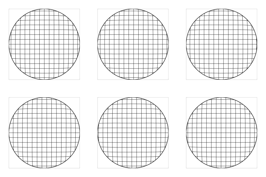
reveals a strong globe effect, though a careful inspection delivers something
interesting: The image appears to be flat in the central part of the
field, then bending away from the observer toward the edge.
A careful observer may even detect a slight
dent in the central part of the image, i.e. it appears to be almost of
concave shape, then bending over and turning convex toward the edges.
This is, of course, the consequence of the rather complex shape of the distortion
curve in Fig. 2.

Figure 3: The dynamics of the moving image
in visual space (computer simulation).
Section 3: Analysis of the observable dynamics
We shall now go ahead and analyze in a more quantitative way what
we have observed. Whenever a binocular is panned, the angle of each
object around us turns into a variable of time. For the case of simplicity,
let us discuss the trajectory of a distant object (e.g., a star), which,
during panning, enters the field of view at the edge, then passes
through the center and finally exits at the opposite side of the field.
In a first step, we evaluate the apparent angle as a function of the
object angle, using Eq. (2):
![\begin{displaymath}
a = \arctan [(V_{rel} + 1) m \tan(A)]\;,
\end{displaymath}](img7.png) |
(5) |
and express the relative distortion through its fourth order polynomial
 |
(6) |
where the coefficients  are consistent with an object angle
in radian. This has to be inserted into Eq. (4)
to yield the perceived distances in the visual field:
![\begin{displaymath}
y = \frac{1}{l} \tan \left\{l\cdot \arctan \left[\left(\sum_{i=2}^{4} p_i A^i + 1\right) m\cdot \tan(A)\right]\right\}\;.
\end{displaymath}](img10.png) |
(7) |
In order to study its properties during panning, we have to evaluate the
radial velocity of the image point in our visual field as a function of
the object angle, yielding
![\begin{displaymath}
\dot y = \frac{m \dot A \left[\cos^{-2} (A) \left( \sum_{i=2...
...=2}^{4} p_i A^i + 1\right) m\cdot \tan(A) \right]^2\right)}\;,
\end{displaymath}](img11.png) |
(8) |
where  is the time derivative of the object angle, i.e. the angular
velocity of panning. It is convenient to define the
characteristic drift ratio (see Ref. 1)
 |
(9) |
as the perceived radial velocity of the image point, scaled
with its velocity at the center of field. In this way, the
speed of the image point becomes independent of the
velocity of panning. With
 |
(10) |
we have
![\begin{displaymath}
\Gamma = \frac{\cos^{-2} (A) \left( \sum_{i=2}^{4} p_i
A^i ...
...=2}^{4} p_i A^i + 1\right) m\cdot \tan(A) \right]^2\right)}\;.
\end{displaymath}](img15.png) |
(11) |
Figure 4:
The characteristic drift ratio (left) and the radial
acceleration (right) of an image point on its trajectory through
the center of field.
|
|
This quantity is plotted in Fig. 4 (left). We observe
that the image point initially exhibits a slight acceleration when
moving away from the center, and is then quickly slowing down beyond
about 2.5 degrees. Our visual perception seems to interpret
changes of the drift velocity, i.e. accelerations, as the
result of an image curvature: Whenever an image point accelerates,
it appears to move closer, and upon deceleration it appears to move
away from the observer. In other words, the image
has got a concave curvature with accelerating image points, and
a convex curvature with decelerating image points. The right
hand side of Fig. 4
displays the derivative of the characteristic drift
ratio,
 |
(12) |
which is nothing else but the perceived acceleration of the
moving image point. The perceived curvature in the animated
Figure 3 has to be interpreted accordingly: In its central part,
the image
is almost flat, perhaps a little bit concave, while toward the edges it appears to bend
away from the observer, thus generating the globe effect of this
binocular.
Summary
Not every binocular has got a 'regular' distortion curve, being consistent with Eq. (1). If this curve is rather complex, as shown in this example of the BPO, then a peculiar panning behavior may show up. Computer simulations of the dynamics in visual space support us in our understanding of the perceived curvature, which in certain cases generates the impression of the globe effect, in considerable detail. For sure, a certain amount of pincushion distortion is required to eliminate the curvature of human visual space. While implementing this distortion, it is desirable to keep the distortion curve as smooth as possible to avoid any spurious curvature effects with the panning binocular. A distortion curve that is consistent with Eq. (1) and a distortion parameter around k = 0.6 is expected to deliver a smooth panning characteristics to most individuals.
Acknowledgment
The author is grateful for inspiring discussions with Daniel Rotter
of the Swarovski GmbH. He thanks the Swarovski labs in Absam for providing
the distortion data of the BPO 7x30.
Appendix: Is visual distortion of the essence?
Doubts have been raised whether or not the visual distortion is eventually
generating the globe effect of this binocular. This is most easily checked out:
The absence of human visual distortion would correspond to a distortion parameter
of l=1 and deliver a flat (Euclidean) visual space. The corresponding
simulation, using the same instrumental distortion curve (Fig. 2), yields the following:

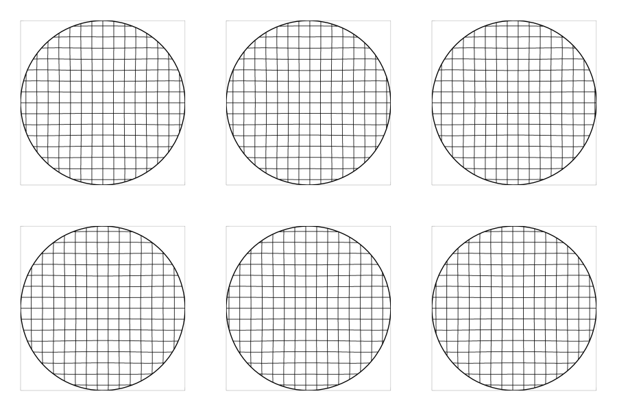
Figure 5: The dynamics of the moving image
in visual space, under the assumption of vanishing visual distortion (l=1, computer simulation).
The globe effect, i.e. the apparent convex shape of the moving image, is
gone. Instead, over most parts of the field, the image
seems to be concave, rather hollow than globe-like, apart from the
outer region where it slightly bends away to turn convex.
This does not coincide with the impression
behind the ocular, or, at least, not to me. We have to consider the fact that the
BPO is rather (in-)famous for its pronounced globe effect. Even though
perception may differ individually, the majority of observers would surely
agree that Fig. 3 represents the visual impression much closer than Fig. 5,
and this would imply the visual distortion, or curvature, being the root of the
perception of the globe effect.
-
-
[1] H. Merlitz, Distortion of binoculars revisited: Does the
sweet spot exist?, J. Opt. Soc. Am. A 27, p. 50 (2010).
Here a PDF version of that paper.
Back Home
Last updated: June 2010

![\includegraphics[width=1.0\columnwidth]{verz.eps}](img5.png)


![\begin{displaymath}
y = \frac{1}{l} \tan \left\{l\cdot \arctan \left[\left(\sum_{i=2}^{4} p_i A^i + 1\right) m\cdot \tan(A)\right]\right\}\;.
\end{displaymath}](img10.png)
![\begin{displaymath}
\dot y = \frac{m \dot A \left[\cos^{-2} (A) \left( \sum_{i=2...
...=2}^{4} p_i A^i + 1\right) m\cdot \tan(A) \right]^2\right)}\;,
\end{displaymath}](img11.png)
![\begin{displaymath}
\Gamma = \frac{\cos^{-2} (A) \left( \sum_{i=2}^{4} p_i
A^i ...
...=2}^{4} p_i A^i + 1\right) m\cdot \tan(A) \right]^2\right)}\;.
\end{displaymath}](img15.png)
![\includegraphics[width=0.5\columnwidth]{drift.eps}](img17.png)
![\includegraphics[width=0.5\columnwidth]{acceleration.eps}](img18.png)
